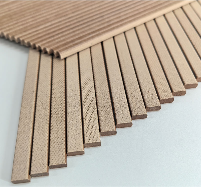
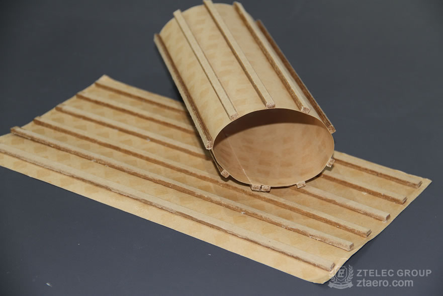
1. Transformer Oil Duct Strips Introduction Transformer Oil Duct Strips are critical structural components inside tr...
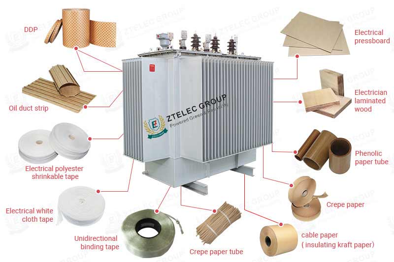
Transformer Oil Duct Strips are critical structural components inside transformers, primarily used to secure windings, maintain oil channel clearance, and optimize heat dissipation. Their design directly impacts the transformer’s mechanical stability, cooling efficiency, and insulation safety.
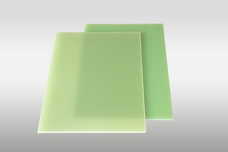
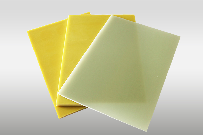
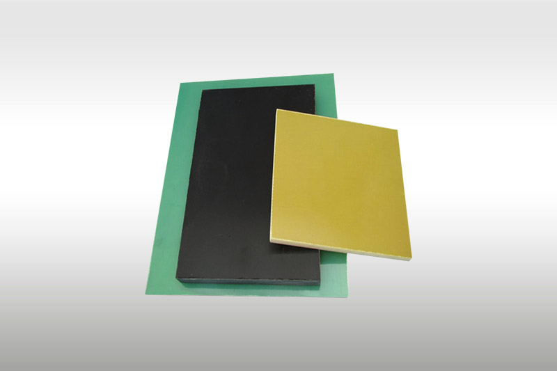
Traditional Design: Made of laminated pressboard, epoxy resin, or other insulating materials as fixed-size monolithic supports, requiring customization for different transformer models.
Innovative Designs:
Adjustable Spacers: Utilize worm gear drives or double-ended threaded rods for height adjustment (±5mm range), compatible with diverse transformer designs.
Hinged Spacers: Employ hinge pins and slots for flexible installation in complex oil paths (e.g., S-shaped channels).
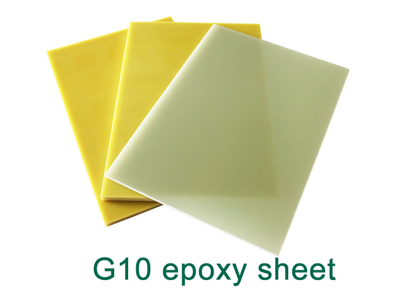
Composite Spacers: Use lightweight, high-strength materials (e.g., glass fiber-reinforced epoxy) for enhanced heat resistance, impact resistance, and corrosion resistance.
Oil-Immersed Transformers:
Winding Fixation: Combine upper/lower positioning rings with columnar spacers to form a stable mechanical support network, preventing short circuits or deformation.
Cooling Optimization: Spacer spacing directly affects oil flow; elongated hole designs (e.g., 20-30mm spacing, 5-8mm diameter holes) increase heat dissipation area.
Dry-Type Transformers:
High-temperature-resistant materials (e.g., Class F, 155°C) prevent softening or deformation.
Special Scenarios:
High-Humidity Environments: Anti-hygroscopic materials (e.g., polyimide composites).
High-Frequency Transformers: Optimize dielectric constants to reduce partial discharge risks.
| Parameter Category | Specifications and Example Data |
|---|---|
| Material Properties | – Laminated pressboard: Compressive strength ≥80MPa, water absorption <5%; – Epoxy resin: Heat resistance 130°C, dielectric strength ≥20kV/mm; – Composites: Impact resistance ≥50kJ/m². |
| Mechanical Performance | – Compressive strength: ≥100MPa (GB/T 9341); – Adjustable spacer synchronization accuracy: ±0.1mm (worm gear drive). |
| Dimensions | – Standard length: 300-1500mm (segmented design); – Cross-section: Round (φ8-20mm), square (10×10mm~30×30mm). |
| Heat Resistance | – Oil-immersed: Class A (105°C), Class F (155°C); – Dry-type: Class H (180°C). |
| Insulation Performance | – Power-frequency withstand voltage: 35kV/min (GB 1094.3); – Lightning impulse withstand: 200kV (1.2/50μs waveform). |
International Standards:
IEC 60076: Specifies insulation, temperature rise, and short-circuit withstand capabilities (e.g., winding temperature rise limit: 65K).
IEEE C57.12.00: General requirements for power transformers, covering mechanical strength and cooling.
ASTM D202: Density (0.8-1.2g/cm³) and dielectric strength testing for insulating pressboard.
Compatibility Assessment:
Adjustable Designs: Select worm gear-driven spacers with ±5mm adjustment range.
Special Environments: Consider low-pressure insulation for high-altitude applications (IEC 60076-15).
Material Selection:
Cost-Effective: Laminated pressboard (small distribution transformers).
High-Performance: Epoxy/composites (large power transformers).
Supplier Qualifications:
Require ISO 9001 certification and third-party test reports (e.g., SGS insulation tests).
Cooling Optimization:
Prioritize spacers with elongated holes (≥30% area ratio), referencing IEEE C57.91 thermal aging models.
Installation Steps:
Pre-Installation Checks: Clean oil channels; verify spacer dimensions (tolerance ±0.5mm).
Positioning: Use non-metallic tools (e.g., nylon hammer) to avoid insulation damage.
Calibration: Synchronize double-ended threaded rods for uniform height (error ≤0.2mm).
Critical Notes:
Insulation Protection: Prevent metal debris ingress (use anti-static gloves).
Stress Relief: Leave 0.5-1mm gaps for hinged spacers to accommodate thermal expansion.
Maintenance:
Inspections: Check for cracks/deformation every 3 years (focus on winding stress points).
Troubleshooting: Replace spacers if oil flow drops ≥20% due to blockages.
Selecting transformer Oil Duct Strips requires balancing mechanical strength, insulation, and cooling efficiency. Innovative adjustable and composite designs are replacing traditional models. Strict adherence to standards (e.g., IEC 60076) and precise installation ensure long-term reliability. For specialized environments (high humidity, high frequency), tailored materials and structures are essential. Future trends focus on smart monitoring and sustainability.
If you are interested in our products,, please send us a message and we will contact you as soon as we receive it. Email: info@ztelecgroup.com whatsApp: +8616650273778

Time:04-24 2025
Time:04-10 2025
© Copyright 2019. All Rights Reserved. Designed by Ztelec group Sitemap